Ultimaker S5 Hub
Welcome to the Ultimaker S5 Hub. Here you’ll find all the information that you’ll need to become proficient in operating the Ultimaker S5.
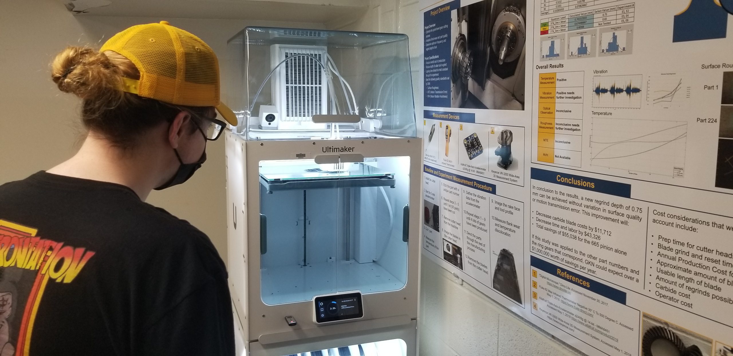
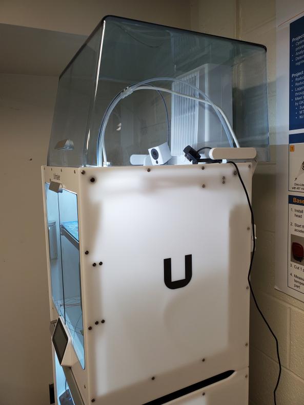
The Ultimaker S5
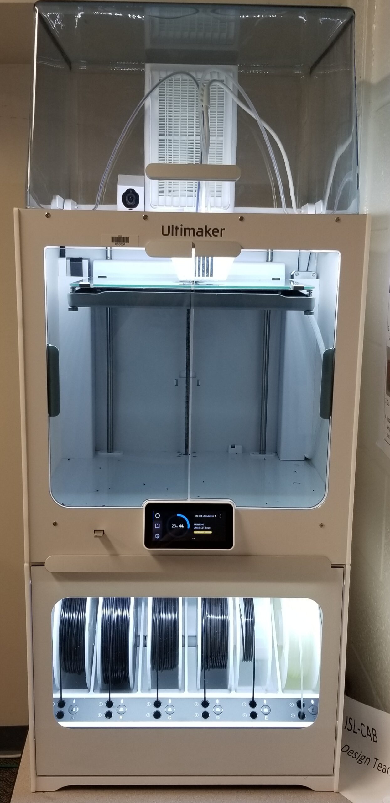
The Ultimaker S5 is the ISL’s first printer. It is capable of printing a wide variety of filaments and is capable of dual extrusion with a wide variety of features. To find more information on the about page on the Ultimaker S5.
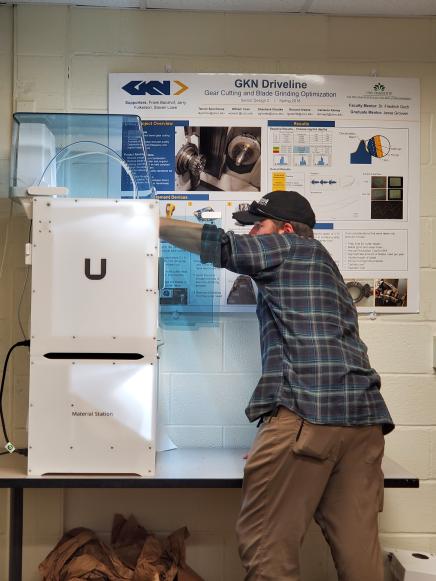
The Material Handler
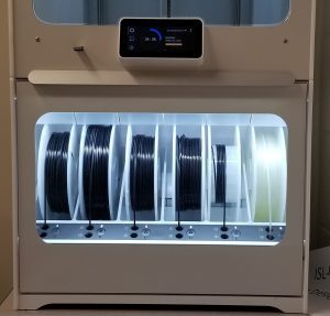
This is an additional accessory that compliments the Ultimaker S5’s amazing capabilities. Being able to automatically swap filaments during the course printing a part, to the many additional features it offers, it is sure to be instrumental to your group’s part versatility. For further information check the about page for the Material Handler.
Image Gallery


Find citations for information
About the Material Handler
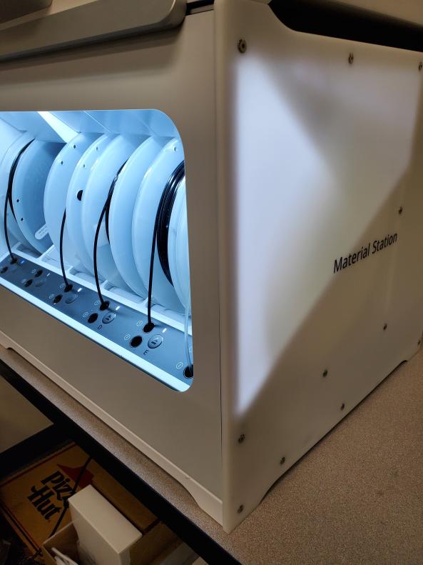
The material handler is useful for the automated swapping filaments while actively printing. It also offers humidity control for safe storage of filaments that may come into help prevent them coming in contact with the moisture in the air.
Further in-depth resources from Ultimaker:
Printing with the Material Station
Automatic Filament Switching
Spool Compatibility
Humidity Control
User Manual
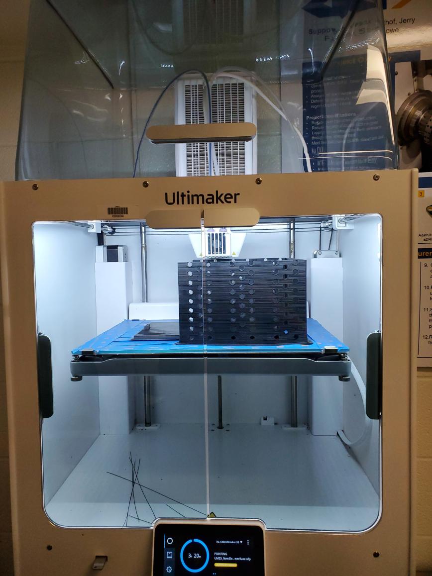
About the Ultimaker S5
This is the Ultimaker S5. It is a very versatile 3D Printer. Having a wide variety of filaments and numerous features makes this a good choice for your 3D printing needs. Capable of dual extrusion, which is helpful for parts with difficult geometry, it adds another layer of versatility to this printer. Easy to use and modular capability allows for it being a good choice for printing many different types of parts. Key features can be found in the various videos below.
Printer Specifications
Further details Printer Specifications can be found in the resources below.
Ultimaker Resources for Printer Specifications
User Manuals:
Basic Training on the Ultimaker S5
This will give you all the basics on learning how to operate the Ultimaker S5 and Slicer Software for preparing a model for print.
Ultimaker Cura
![]()
Where to find Ultimaker Cura:
Ultimaker Support on setting up the software
Ultimaker Support guide for the slicer
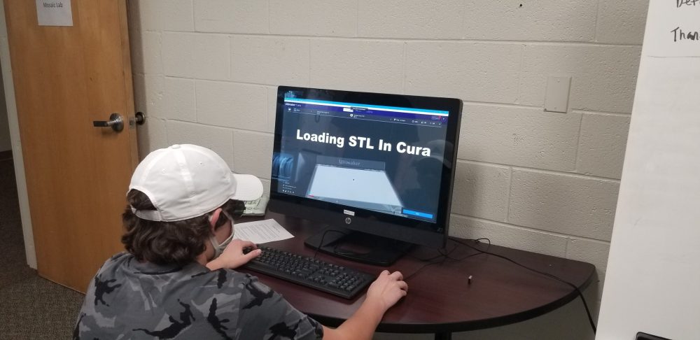
Model Uploading, Manipulation, and Slicing
This video will entail uploading and manipulating your model in the slicer software and saving it to the USB.
Please save sliced models to the USB found in the Ultimaker S5.
Print Bed Preparation
This video will show how to prep the print bed in the Ultimaker S5.
Starting a Print
This video will show you how to print your file from the USB.
https://youtu.be/z76RXY1y014 Printing a File Using a USB
It may be more ideal to use a flash drive to print files. In that case, the steps below will show how to save the file from the Cura slicer to a USB device and then print the file using the USB device.
Insert the USB on to the Ultimaker S5 and select the print from the touch screen (leave the USB in the printer for the entire duration of the print)
Ensure that the stl file is correctly displayed on the Cura slicer and ready for printing. (Refer to the Loading STL in Cura video for more information)
Removing the Print Bed and Object
This video will show you how to remove the print bed from the Ultimaker S5 and your object from the print bed.
Cleaning the Print Bed
This video will show you how to clean the print bed.
Re-Inserting the Print Bed
This video will show you how to re-insert the bed into the Ultimaker S5.
Advanced Training Hub for the Ultimaker S
This module will walk you through more advanced settings of the Ultimaker S5 and adjusting factors for operation.
Loading/Unloading/Changing Print Cores
Print Core Filament Compatibility Table
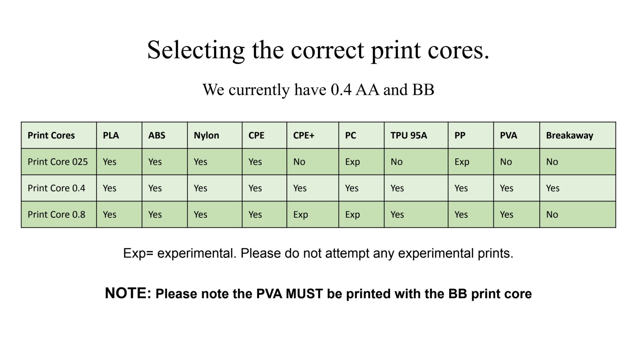
Use this table to find out what size print core your filament is compatible with.
Loading/Unloading Filaments from the Ultimaker S5 Printer
Removing Support Material
Extract any remaining support material from a model using Needlenose pliers.
Be care not to damage parts during removal.
Advanced Slicer Settings
Quality
Layer Height
Height of each printing layer in millimeters. As one may expect, higher values will result in a lower resolution but slower print and vice versa for lower values.
Initial Layer Height
Height of the initial printed layer in millimeters. Generally, a thicker initial layer will result in better build plate adhesion.
Line Width
Width in millimeters of each printed line of filament. Usually will be set to the width of your selected nozzle, although it can be reduced to improve print resolution if need be.
Wall Line Width
Width of a shell’s line of filament, measured in millimeters
Top/Bottom Line Width
Width of a single line of filament on the top or bottom layers of a print, measured in millimeters
Infill Line Width
Width of a single line of infill material, measured in millimeters
Initial Layer Line
Represented as a percentage multiplier of the standard line width. Much like initial layer height, wider base lines can result in better adhesion.
-
Width
- Height of each printing layer in millimeters. As one may expect, higher values will result in a lower resolution but slower print and vice versa for lower values.
Shell
Wall Thickness
Thickness of the exterior walls of the print measured in millimeters. Cura divides this measurement by the overall line width to find the number of exterior walls to be used for a particular print.
Wall Line Count
A custom value for the number of exterior walls that can be designated if necessary
Top/Bottom Thickness
Thickness in millimeters of the top and bottom layers of a given print. Cura divides this measurement by the overall layer height to determine the total number of top and bottom exterior layers. Note, this option can be divided into individual measurements for top and bottom if necessary.
Optimize Wall Printing Order
When checked, this setting will slice the model in such a way that minimal retractions are used and less distance is traveled when printing exterior shells. Generally left on, although it can affect print time for certain models.
Fill Gaps between Walls
When enabled, fills gaps between individual shells with infill if said gap is not wide enough for an additional shell.
Horizontal Expansion
Measured in millimeters, influences the amount of horizontal offset allowed for a particular print to account for under or oversized features such as holes.
Enable Ironing
Allows the hot end to run over the top surface of a model without extruding material to melt the top layers of filament together for a smoother surface finish. Can greatly influence print time depending on the size of a particular model.
Infill
Infill Density
Adjusts the density of infill for a given print, ranging from 0 to 100%, the former meaning the print is completely hollow and the latter resulting in a print that is completely solid. Influences print time and material used as well as most subsequent infill settings.
Infill Line Distance
Distance between infill lines measured in millimeters. This setting is normally calculated by the values set for infill density and infill line width, however a custom value can be set if desired.
Infill Pattern
Varying options of infill patterns ranging from cubic, hexagonal, gyroid, concentric, etc. Differing patterns offer variances in print strength versus material used. Generally can be left alone as the slicing program will select the most appropriate pattern for a selected density
Infill Line Multiplier
Divides infill lines from one to several if needed, resulting in a stronger model. Will increase print time and material usage.
Infill Overlap Percentage
Defines the amount of overlap between the infill and exterior wall filament lines. Higher overlap ensures better adhesion between the walls and infill but requires more material.
Infill Layer Thickness
Thickness per layer of infill lines in millimeters. Generally should remain the same as standard layer height to ensure consistency across the entirety of the print.
Gradual Infill Steps
Defined by the number of times to reduce infill density between the top and bottom layers. Higher values will result in less infill at the bottom of the print and more at the top whereas a value of zero will result in totally uniform distribution of infill material through out the model. Can reduce print time and material used in exchange for lowered print strength.
Material
Printing Temperature/Printing Temperature Initial Layer
Temperature the hot end is heated to for the main print and initial layers respectively. Higher initial layer temperature can improve flow and bed adhesion. Temperatures will vary from material to material, therefore users will need to refer to the spool itself for optimal operating temps.
Initial Printing Temperature/Final Printing Temperature
Allows the printer to operate within a gradient from the beginning to the end of the print if needed. Setting will generally be governed by the base print temperature unless otherwise altered.
Build Plate Temperature/Build Plate Temperature Initial Layer
Allows the build plate, if supported, to heat itself to a set temperature to improve adhesion for a print. A higher initial temperature can ensure better adhesion for the first layer while lower temperatures will ensure less warping overtime. A value of zero will disable bed heating.
Flow/Initial Layer Flow
Flow is represented by a percentage scale from 0-100% for most features represented on the print such as infill, inner and outer walls, supports, etc. The setting will configure the amount of filament the extruder will provide during the process of printing. Normally can be left at 100%, flow settings are normally used as a compensatory measure in the event of other issues during printing.
Speed
Print Speed
Generalization of the hot end movement speed and extruder speed during printing. Higher values result in a faster but uglier print, vice versa for lower values. Governs most other speed options.
Travel Speed
Speed at which the hot end will move when not actively printing. Higher values can result in lower print times but do present a risk of having the hot end crash into the print, resulting in a failure.
Initial Layer Speed
Print speed for the initial layers. Lower speeds will improve bed adhesion for difficult prints.
Skirt/Brim Speed
Speed at which bed adhesion features will be printed. Generally will be the same as your initial layer speed, however a different speed may be desired depending on a particular print.
Number of Slower Layers
Designates the number of layers to be printed at your initial layer speed to improve adhesion if needed. Normally set to a value of 2.
Equalize Filament Flow
When checked, modifies the g-code of a particular print to instruct the printer to print thinner lines faster to maintain a uniform material extrusion rate. Can improve print times at a sacrifice of quality depending on the finer features of a particular model.
Allows the user to change preset values for hot end “jerk” or rapid changes in velocity. Can improve print time at a cost of print quality.
Enable Acceleration Control
Allows the user to change the preset values for hot end acceleration to improve print time at a cost of quality.
Enable Jerk Control
Allows the user to change preset values for hot end “jerk” or rapid changes in velocity. Can improve print time at a cost of print quality.
Travel
Enable Retraction
Allows the extruder to retract filament further back into the hot end when moving over a non printed area to prevent stringing.
Retract at Layer Change
When checked, allows the extruder to retract filament when rising to the next layer of the print. Generally not recommended except in special circumstances as the hot end will already be over a printed area when changing layers.
Retraction Distance
Measured in millimeters, governs the amount of filament retracted by the extruder when needed. Larger values will help to prevent stringing but can present issues as the extruder must force the filament back to the hot end to resume printing.
Retraction Speed
Governs the speed at which filament is retracted and primed during the retraction process. Similar pros and cons to retraction distance.
Retraction Extra Prime Amount
During the priming process, a small amount of filament can leak or ooze through the hot end which can produce unnecessary features or begin the development of a blob of filament on the nozzle itself. This setting, measured in cubic millimeters, allows a user to tune the exact amount of material primed to ensure a clear nozzle before printing.
Retraction Minimum Travel
Measured in millimeters, this setting governs the absolute minimum distance that must be covered by the printhead to require a retraction at all. Helps to reduce the total number of retractions over the course of a print.
Maximum Retraction Count
Sets a hard cap on the number of retractions that can be performed on a set length of filament in order to reduce wear on the filament itself which can introduce a whole host of issues such as extruder/hot end jams or snagging of the filament within the Bowden tube.
Minimum Extrusion Distance Window
The ordained length of filament on which the maximum retraction count will act on. This value should be set to roughly the same as the retraction distance so that the effective number of retractions on the same piece of filament is reduced.
Combing Mode
When enabled, combing will keep the nozzle within printed areas during the printing process to minimize the need for retractions. Can be tuned to only affect certain areas of the print if needed.
Retract before Outer Wall
When checked, the printer will always retract the filament when starting an exterior shell to ensure no improper deposition of material.
Avoiding Printed Parts/Supports When Traveling
Adjusts the sliced model to instruct the hot end to avoid already printed layers of both the part and supports to prevent printing errors. Can only be enabled if combing is already enabled.
Travel Avoid Distance
Designates a set distance in millimeters for the nozzle to avoid printed parts and supports when making travel moves.
Layer Start X
A designated X offset, measured in millimeters on where to begin printing each subsequent layer for a particular part. Normally set to a value of 0.
Layer Start Y
A designated Y offset, measured in millimeters on where to begin printing each subsequent layer for a particular part. Normally set to a value of 0.
Z-Hop When Retracted
Allows the z-axis of a given printer to increase slightly during retraction moves to ensure maximal clearance between the nozzle and print surface.
Cooling
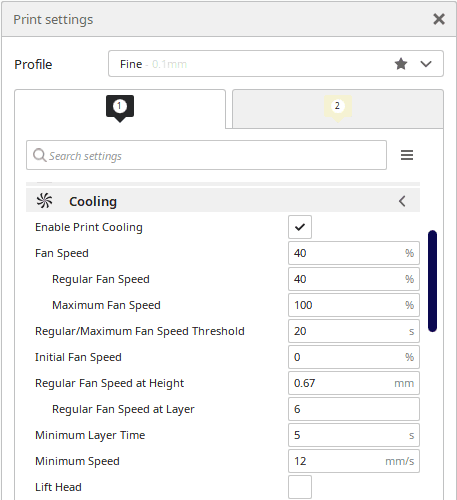
Enable Print Cooling
Enables the print cooling fans while printing. Purpose is to improve print quality on layers with short layer times and bridging/overhangs.
Fan Speed
The speed at which the print cooling fans spin (Based on percentage).
Regular Fan Speed
The speed at which the fans spin before hitting the threshold. When a layer prints faster than the threshold, the fan speed gradually inclines towards the maximum fan speed.
Maximum Fan Speed
The speed at which the fans spin on the minimum layer time. The fan speed gradually increases between the regular fan speed and the maximum fan speed when the threshold is hit.
Regular/Maximum Fan Speed Threshold
Layer time which sets the threshold between regular fan speed and maximum fan speed. Layers that print slower than this by default use regular fan speed whereas faster layers gradually increases towards maximum fan speed.
Initial Fan Speed
Speed at which the fans spin at start of print. In subsequent layers, the fan speed is gradually increased up to the layer corresponding with to Regular Fan Speed at Height.
Regular Fan Speed at Height
Height at which the fans spin on regular fan speed. At the layers below, the fan speed gradually increases from Initial Fan Speed to Regular Fan Speed.
Regular Fan Speed at Layer
Layer at which the fans spin on regular fan speed. If regular fan speed at height is set, this value is calculated and rounded to a whole number.
Minimum Layer Time
Minimum time spent in a layer. This forces the printer to slow down, to at least spend the time set here in one layer; allowing the printed material to cool down properly before printing the next layer. Layers may still take shorter than the minimal layer time if Lift Head is disabled and if the Minimum Speed would otherwise be violated.
Minimum Speed
The minimum print speed, despite slowing down due to the minimum layer time. When the printer would slow down too much, the pressure in the nozzle would be too low and result in bad print quality.
Lift Head
When minimum speed is hit because of minimum layer time, lift the head away from the print and wait the extra time until the minimum layer time is reached.
Support
Generate Support
Generate structures to support parts of the model which have overhangs. Without these structures, such parts would collapse during printing.
- Affects the Support Wall Line Count & Support Density
- Tree Support v Normal Support
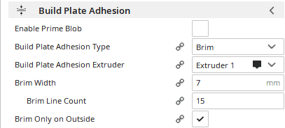
Build Plate Adhesion
Enable Prime Blob
Determines whether to prime the filament with a blob before printing. Turning this setting on will ensure that the extruder will have material ready at the nozzle before printing. Printing Brim or Skirt can act like priming, in which case turning this setting off will save time.
Build Plate Adhesion Type
Different options that help to improve both priming the extrusion and adhesion to the build plate. Brim adds a single layer flat area around the base of your model to prevent warping. Raft adds a thick grid with a roof below the model. Skirt is a line printed around the model, but is not connected to the model.
Build Plate Adhesion Extruder
The extruder train to use for printing the skirt/brim/raft. Used in multi-extrusion.
Brim Width
The distance from the model to the outermost brim line. A larger brim enhances adhesion to the build plate, but also reduces the effective print area.
Brim Line Count
The number of lines used for a brim. More brim lines enhance adhesion to the build plate, but also reduces the effective print area.
Brim Only on Outside
Only print the brim on the outside of the model. This reduces the amount of brim you need to remove afterwards, while not reducing the bed adhesion as much.
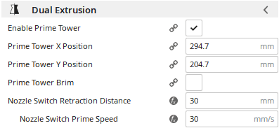
Dual Extrusion
Enable Prime Tower
Print a tower next to the print which serves to prime the material after each nozzle switch.
Prime Tower X Position
X-Coordinate of the position of the Prime Tower.
Prime Tower Y Position
Y-Coordinate of the position of the Prime Tower.
Prime Tower Brim
Prime towers might need extra adhesion afforded by brim even if the model itself doesn’t. Not compatible with “Raft” adhesion type.
Nozzle Switch Retraction Distance
The amount of retraction when switching extruders. Set to 0 for no retraction at all. This should generally be the same as the length of the heat zone.
Nozzle Switch Prime Speed
Speed at which the filament is pushed back after a nozzle switch retraction.
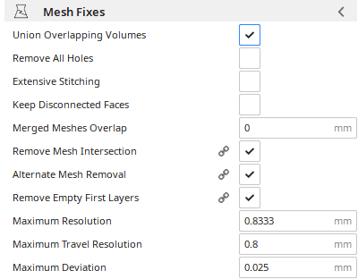
Mesh Fixes
Union Overlapping Volumes
Ignores the internal geometry arising from overlapping volumes within a mesh and prints the volumes as one. This may cause unintended internal cavities to disappear.
Remove All Holes
Remove the holes in each layer and keep only the outside shape. This will ignore any invisible internal geometry. However, it also ignores layer holes which can be viewed from above or below.
Extensive Stitching
Tries to stitch up open holes in the mesh by closing the hole with touching polygons. This option can introduce a lot of processing time.
Merged Meshes Overlap
Make meshes which are touching each other overlap a bit. This makes them bond together better.
Remove Mesh Intersection
Remove areas where multiple meshes are overlapping with each other. This may be used if merged dual material objects overlap with each other.
Alternate Mesh Removal
Switch to which mesh intersecting volumes will belong with every layer, so that the overlapping meshes become interwoven. Turning this setting off will cause one of the meshes to obtain all of the volume in the overlap, while it is removed from the other meshes.
Remove Empty First Layers
Remove empty layers beneath the first printed layer if they are present. Disabling this setting can cause empty first layers if the Slicing Tolerance setting is set to Exclusive or Middle.
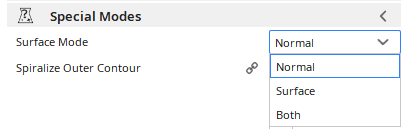
Special Modes
Surface Mode
Treats the model as a surface only, a volume, or volumes with loose surfaces. The normal print mode only prints enclosed volumes. “Surface” prints a single wall tracing the mesh surface with no infill and no top/bottom skin. “Both” prints enclosed volumes like normal and any remaining polygons as surfaces.
Spiralize Outer Contour
Spiralize smooths out the Z move of the outer edge. This will create a steady Z increase over the whole print. This feature turns a solid model into a single walled print with a solid bottom. This feature should only be enabled when each layer only contains a single part.
Experimental Settings
Make Overhang Printable
Change the geometry of the printed model such that minimal support is required. Steep overhangs will become shallow overhangs. Overhanging areas will drop down to become more vertical.
Use Adaptive Layers
Adaptive layers computes the layer heights depending on the shape of the model.
Post Processing
Much like other manufacturing methods, there exists a slew of post processing techniques available for 3D printing, although some techniques may be more suitable than others depending on the material and its properties. Shown below are a number of post processing techniques that can be used
Joining Parts
- ABS Welding
- As stated in the material guidelines, ABS is very soluble in the presence of esters and ketones, most prominent of which being acetone which is often used as paint thinner. By applying a small amount of acetone to a joint between two plastic parts, the solvent acts similarly to plastic cement, melting the material before allowing the two pieces to join as one with a joint as strong as the original material. Keep in mind that this process will only work for ABS as PLA will begin to degrade in the presence of acetone due to its chemical composition.
- Gluing
- For most other materials such as PLA, PETG, or Nylon, the usual plan of attack for joining two parts will be the application of adhesives such as glue or epoxy depending on your intended applications. Keep in mind when using certain epoxies or hot glue on temperature sensitive materials, such as PLA, you may encounter warping as the plastic will soften in the presence of higher temperatures.
Refining Surface Finish
- Dry Sanding/Wet Sanding
- Sanding is a tried and true method of increasing surface finish that unfortunately will demand the most time out of any other process. As the name suggests, using a progressive line of rough to fine grit sandpaper will remove blemishes, unneeded features, and layer lines until a smooth surface finish is achieved. Be mindful of course of the amount of material that is removed through these abrasive techniques and ensure that you do not unintentionally sand too much.
- Application of Heat
- The application of heat can be a quick and easy option for smoothing the surface finish of temperature sensitive materials such as PLA. Temperatures in the neighborhood of 60-70 degrees centigrade will cause the plastic to become more pliable and allow some rougher features to reach a smoother finish.
- Epoxy Resin
- Epoxy resin is a popular option for producing a glossy finish on materials such as PLA that cannot be smoothed by acetone exposure like ABS. When applied to the surface through brushing, epoxy resin will fill in small gaps and defects, such as the ones between layer lines before hardening into a smooth finish that can be sanded further if desired.
- Acetone Vapor Exposure
- One of the most popular surface finishing processes for ABS is the exposure of the model to acetone vapors which will cause the outer surface of the print to begin melting together into a singular surface. This can be performed by leaving an open container of acetone underneath the suspended model inside of a sealed space as the vapors produced by acetone are not only toxic but also flammable. Recommended exposure time ranges from 10 to 20 minutes, although different times may be required depending on the size of a particular print. It’s very important to ensure that your print is not over exposed as it will begin to deform the more the solvent vapors are allowed to break down the material.
- THF Vapor Exposure
- Much like ABS, THF (tetrahydrofuran) is a highly caustic solvent that is more suitable for usage on PLA and avoids the deformation caused by the usage of acetone on the material. The process is much the same however, exposing the print to vapors of the solvent for a set period of time will cause the surface features to form into one smooth finish albeit an exposure of too long will cause deformation that can destroy the print. Again, much like acetone, THF and the vapors it produces are highly toxic, so heavy ventilation is recommended if this method is employed.
Model Database and Directory
Below are a number of different resources for finding 3D parts.
File Database
3rd Party 3D File Sources Directory
Calibration Test Print Files
Located below is a list of the various calibration print files. These images will redirect you to the respective links to download them.
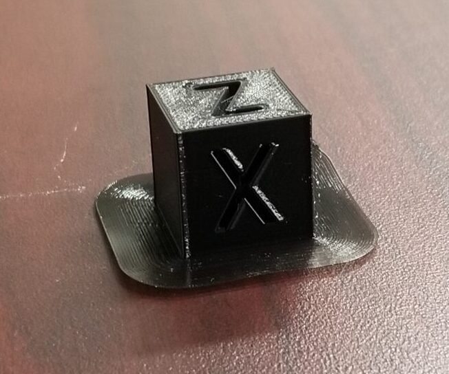
Calibration Cube
Author: by iDig3Dprinting January 19, 2016
Concentric Circles

Author: Ash-win Mathur of ISL-CAB
All in One Test Print:
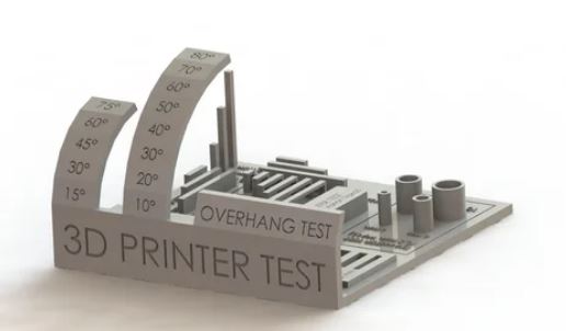
Author: by majda107 November 19, 2017
Torture Tower:
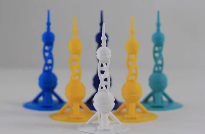
Author: by Polymaker_3D January 26, 2017
Summer Camp Print Files
Print files for the ISL’s Summer Camp
Airplane Model:
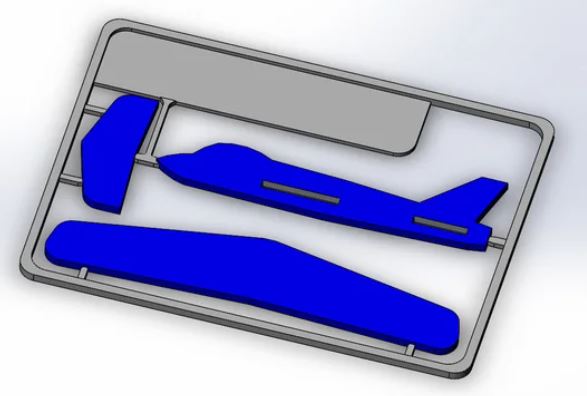
Models and Images by: tmetal June 17, 2015
Pull Copter:
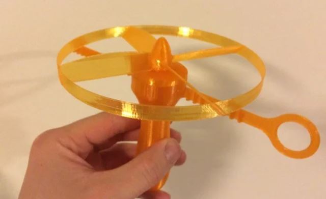
Models and Images by: Davidcolsson April 27, 2014
Rubber Band Powered Car:
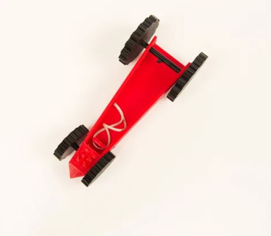
Models and Images by: MakerBotPartnerLibrary October 15, 2015
Weather Vane:
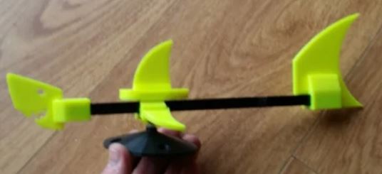
Models and Images by: Southspear April 13, 2017
Tic Tac Toe:
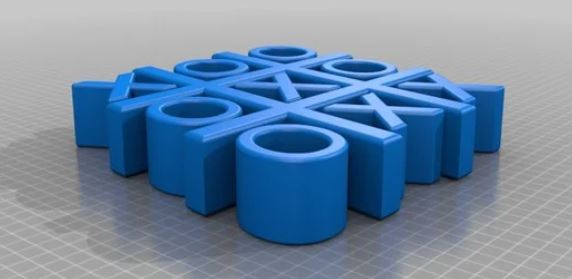
Models and Images by: Ahmsville September 14, 2018
UNC Charlotte Logo:
![]()
Models and Images by: kbmanning98 October 18, 2020
Filament Database
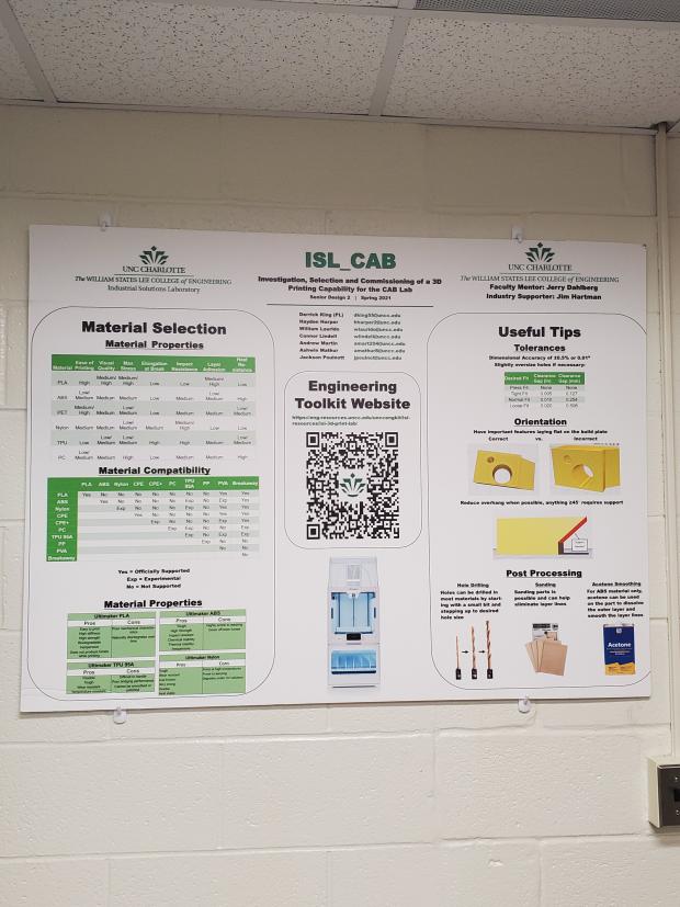
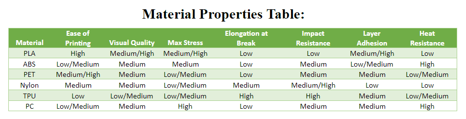
Located below is a Material Properties Comparison Table for quick and easy determination of Material Properties side by side.
Located below is the filament compatibility Chart, which shows which filaments are compatible for support filament:
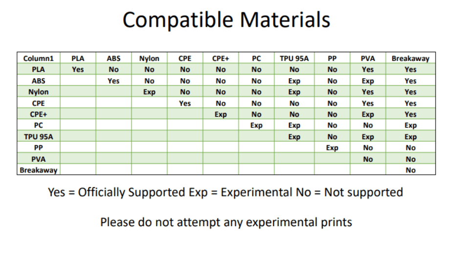
Further Compatibility Information:
Welcome to the filament database compiled by ISL_CAB. Featured below are many of the filaments compatible with the Ultimaker S5.
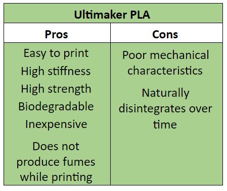
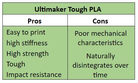
Ultimaker PLA
PLA (Polyactic Acid):
Overview:
This material is a thermoplastic aliphatic polyester and it is the primary natural raw material used in 3D printing. PLA will be less durable, more fragile, and more sensitive to heat than other materials like ABS.
Application:
The main applications for this material are toys, figurines, non-functional prototypes, etc. It is not as toxic compared to ABS.
Pros and Cons:
Supports:
PLA, PVA, Breakaway Support
Ultimaker Resource:
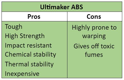
Ultimaker ABS
ABS (Acrylonitrile Butadiene Styrene):
Overview:
ABS is lightweight and has good impact strength; it is abrasion resistant and affordable. ABS material has a good surface quality and is flame retardant.
Application:
Applications include printed enclosures for electrical or electronic assemblies, sports equipment, parts for the automotive industry, or the medical sectors. Many plastic end-products can be manufactured using ABS material.
Pros and Cons:
Processing:
A well ventilated area is ideal for post-processing. Simple sanding and polishing prints.
Supports:
ABS, TPU 95A*, PVA*, Breakaway Support
Ultimaker Resource:
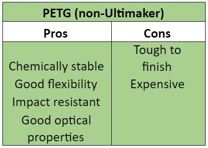
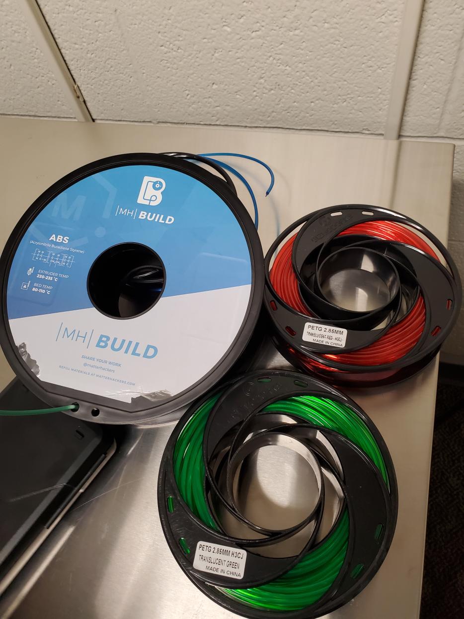
Non-Ultimaker PETG
PETG (Polyethylene Terephthalate Glycol):
Overview:
PETG is well-suited for fabrication techniques like die cutting, routing, and bending. PETG is a thermoplastic polyester that provides significant chemical resistance, durability, and excellent formability for manufacturing. It’s extremely strong and has great chemical resistance. This allows it to print objects that can sustain high temperature, food-safe applications, and exceptional impact.
Application:
It is commonly used in single use and reusable drinking bottles, cooking oil containers, and FDA-compliant food storage containers. However, PETG is also found across the medical field; its rigid structure allows it to survive harsh sterilization processes, making it a perfect material to be used in medical implants, as well as pharmaceutical and medical device packaging.
Pros and Cons:
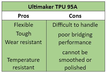
Ultimaker TPU
TPU (Thermoplastic Polyurethane):
Overview:
TPU possesses rubber-like elasticity, high tear and abrasion resistance, high elongation at break as well as thermal stability. Combining the properties of both plastic and rubber, TPU can produce elastic, highly durable parts that can be easily bent or compressed.
Application:
TPU is ideal for producing accessories, such as phone cases, and footwear components. With its high chemical resistance to oils and greases, TPU is also ideal for automotive applications like seals, gaskets, plugs, tubes and protective applications.
Pros and Cons:
Supports:
TPU 95A*, PVA*, Breakaway Support*
Ultimaker Resource: TPU 95A
Ultimaker Resource: TPU 95A SDS
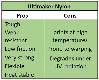
Ultimaker Nylon
Nylon:
Overview:
The prints made from nylon filaments are usually resistant to wear while also having high flexibility. Nylon 3D printer plastic produces tough parts that can tolerate shock along with high levels of impact resistance.
Application:
Applications include high tensile strength moving parts like gears and rollers, production parts like intake manifolds, and parts constantly in contact with others due to its resistance to abrasion.
Pros and Cons:
Supports:
Nylon*, TPU 95A*, PVA, Breakaway Support
Ultimaker Resource:
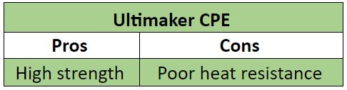
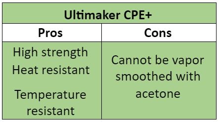
Ultimaker CPE
CPE (Co-Polyester):
Overview:
CPE displays great resistance to chemicals and oils as well as temperature resistance, weather resistance, and good mechanical properties. It has good flexural strength, tensile strength, high impact strength and hardness.
Application:
CPE has a wide range of possible applications due to being FDA-approved for packaging in the food and medical industries.
Pros and Cons:
Supports:
CPE, PVA, Breakaway Support
Ultimaker Resource:
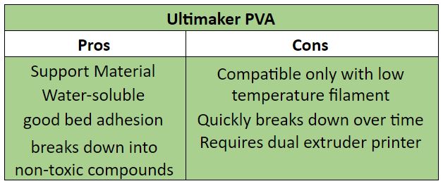
Ultimaker PVA
PVA (Polyvinyl Alcohol):
Overview:
PVA is a water-soluble polymer that is biodegradable and nontoxic. It is resistant to oil as well as grease and solvents, and has excellent adhesive properties. It has high tensile strength and flexibility.
Application:
PVA is commonly used in the production of paper, adhesives, dissolvable packaging such as those seen in single use detergent capsules, printing, eye drops, and textiles.
Pros and Cons:
Supports:
N/A
Other Resources:
Ultimaker Resource:
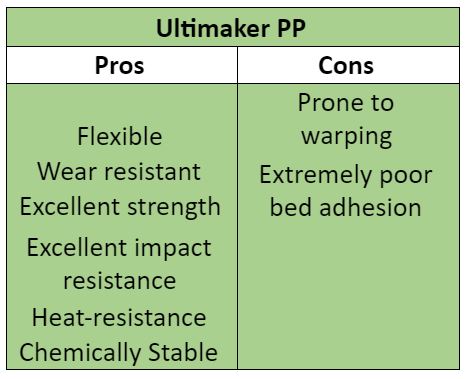
Ultimaker PP
PP (Polypropylene):
Overview:
For 3D printing, PP is great for anything that needs to be light, water-tight, or durable. It’s great for its translucency as well as its resistance against chemicals and fatigue.
Application:
PP is often used in household plastic containers due to it being safe for food and microwaveable interactions.
Pros and Cons:
Supports:
PP*
Ultimaker Resource:
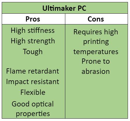
Ultimaker PC
PC (Polycarbonate):
Overview:
Polycarbonate (PC) refers to a group of plastics that are known for their strength, toughness, and heat resistance. It’s ability to withstand torsional stress is superior to other thermoplastics, and it’s flexible enough to be machine bendable at room temperature.
Application:
PC is used in many application areas, including engineering parts, DVDs, and “bulletproof glass”. Due to its transparency, PC can be used to prototype windows and other clear products that would cost much more if produced with other materials.
Pros and Cons:
Supports:
PC*, TPU 95A*, Breakaway Support*
Ultimaker Resource:
Ultimaker CF
CF (Carbon Fiber):
Overview:
Carbon fibers serve to increase the durability of the product printed from the filament in terms of stiffness and tensile strength. The main strengths of carbon fiber lie in its excellent strength-to-volume ratio and very high strength-to-weight ratio; giving excellent rigidity and durability to materials while being much lighter compared to more traditional durable materials such as wood, steel, or aluminum with the bonus of not expanding due to temperature. It also exhibits very good resistance against corrosion and chemical degradation.
Application:
Applications for carbon fiber include any object that requires a high strength while also demanding the lightest weight possible. This could include objects such as bicycle frames, car parts, sporting equipment, and functional prototypes.
Generic Filament
Generic Material:
Manufacturer Resources for using Generic Filament:
Ultimaker Resource: